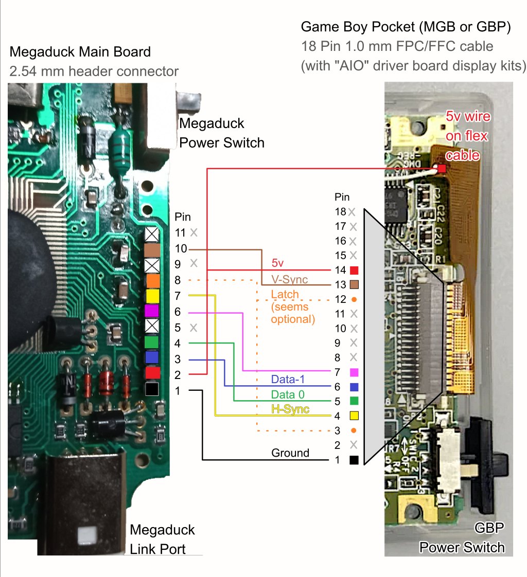
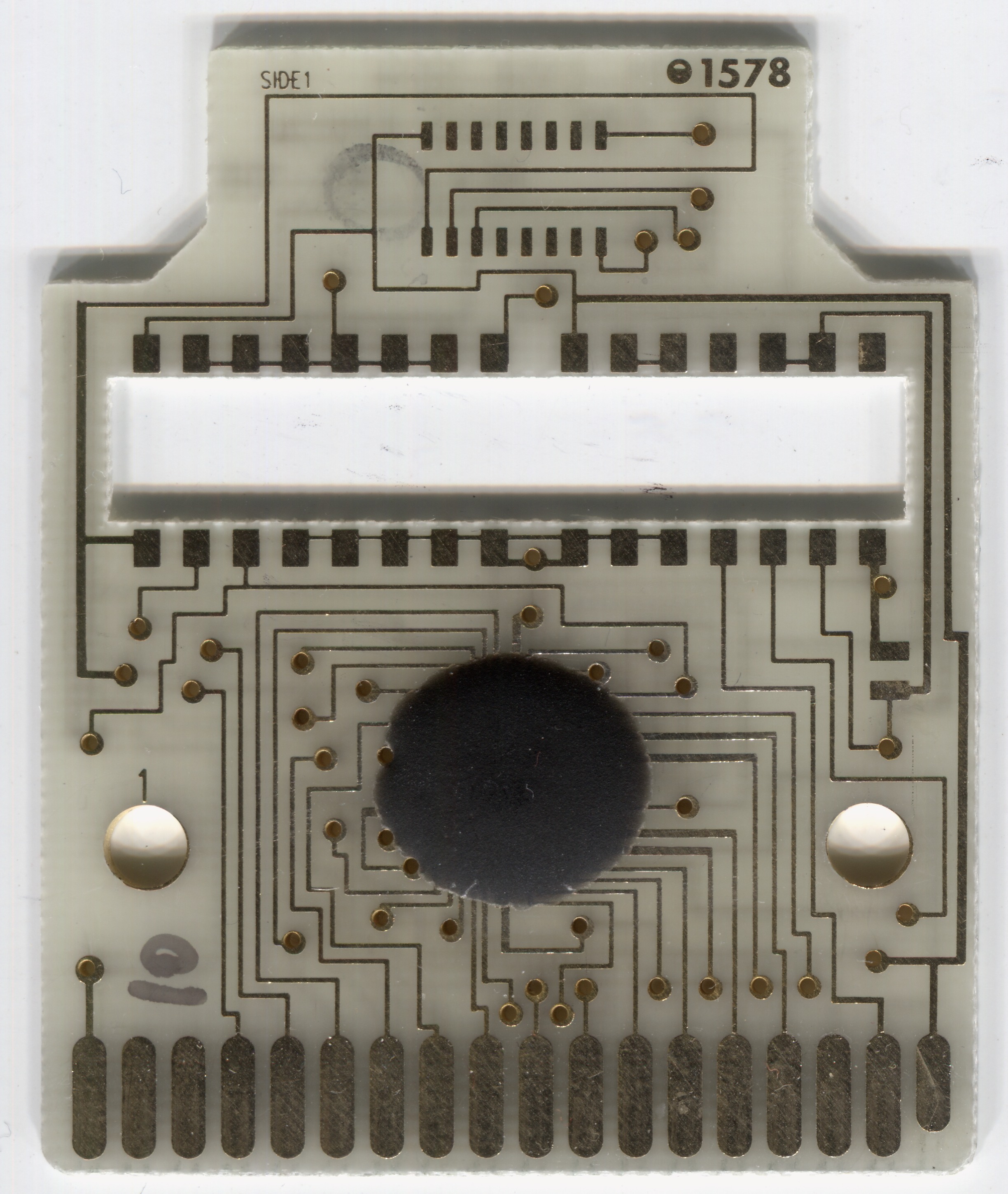
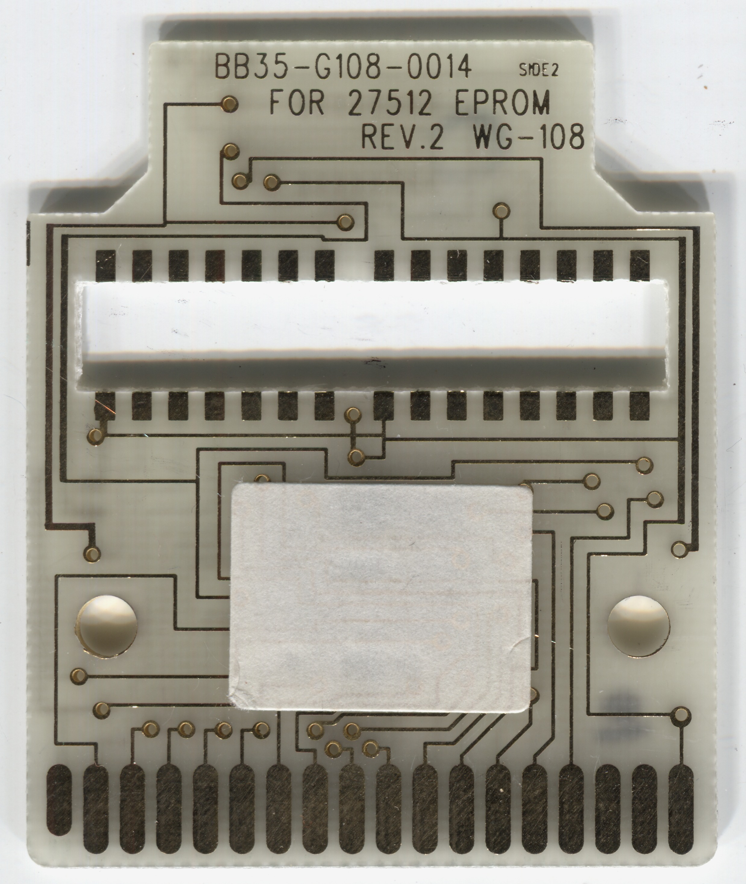
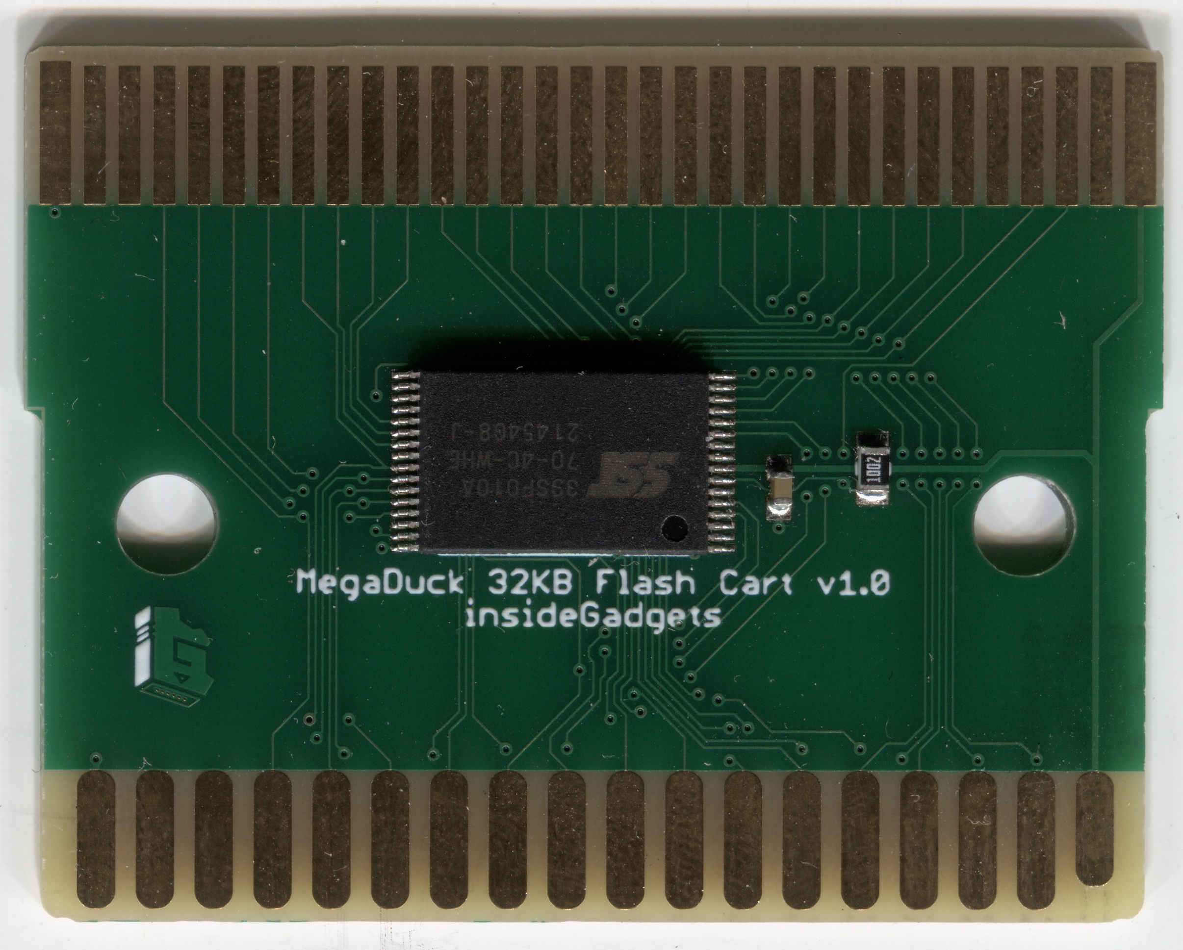
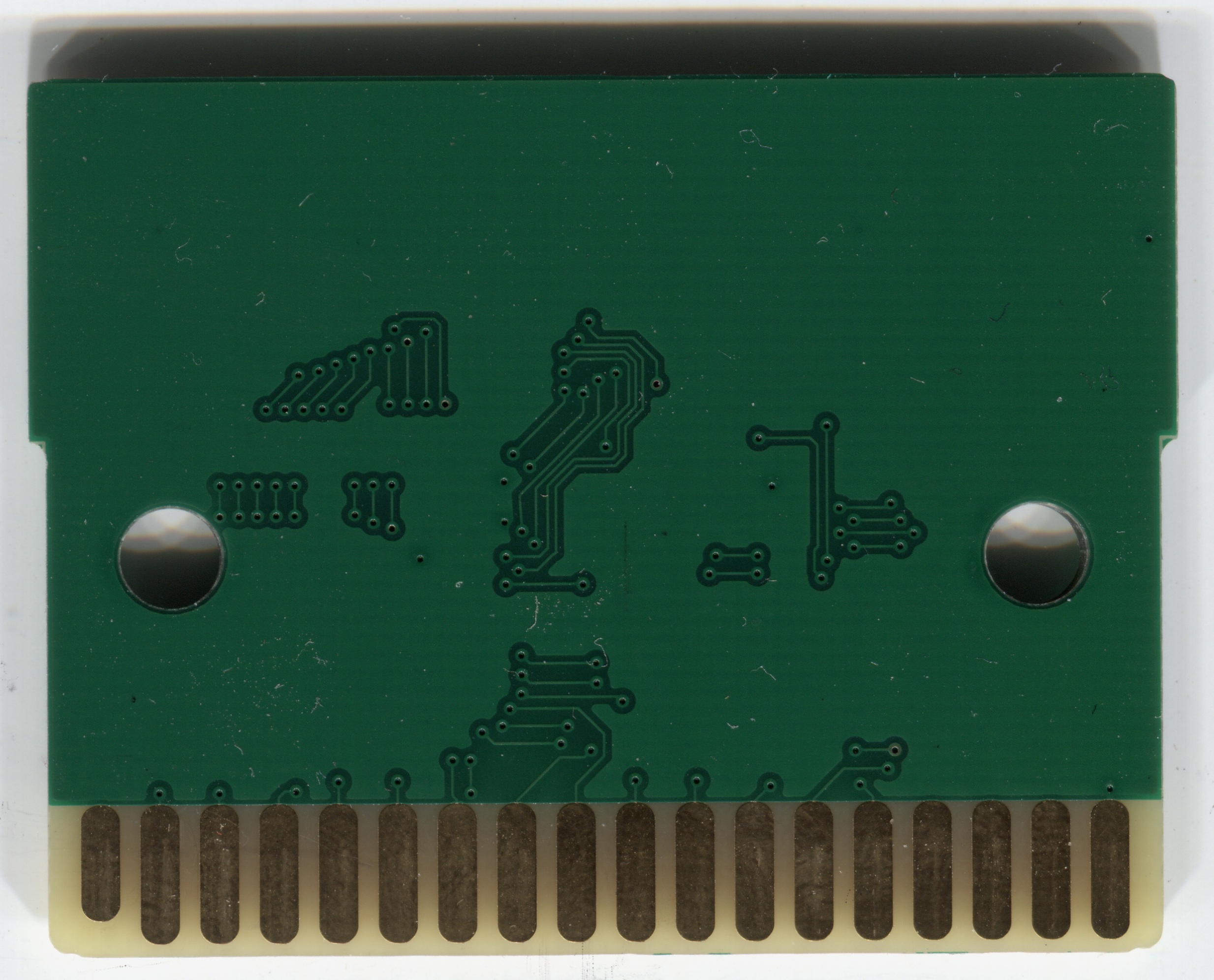
A collection of technical information and resources for the Mega Duck console brought together in one place. Much of it researched by others, some by me (minor sound reg fixes, laptop model docs, some ports and patches, etc).
Sean Riddle, Ruud van Falier, Nitro2k, Toxa, Youkal3, Zwenergy, Inside Gadgets, Kuddel, ManCloud
Patches for running Game Boy games on the MegaDuck
With the use of a connector style adapter a Mega Duck and a Game Boy can exchange data over their link ports.
Diagram showing the link port receptacle*1 pinout when looking at the side of the console:
      Front of console
-----------------------------------
                                   |
--------      -----------------    |
 volume |    | CLK  SIN  VCC*2 |   |
 dial   |    | GND   -   SOUT  |   |
--------      -----------------    |
                                   |
-----------------------------------
       Back of console
Handheld
Laptop
| Extension | Informal # | Switchable ROM Bank | Max | ROM Bank Range | SRAM Bank | Max | SRAM Bank Range | SRAM Reg Style |
|---|---|---|---|---|---|---|---|---|
.duck,.bin |
fixed | 32K | none | 0 | ||||
.md0 |
0xE0 |
32K (0x0000-0x7FFF) |
512K | 0 - 15 | 8K | 32K | 0 - 3 | MD0 |
.md1 |
0xE1 |
32K (0x0000-0x7FFF) |
64K | 0 - 1 | none | 0 | ||
.md2 |
0xE2 |
16K (0x4000-0x7FFF) |
256K | 1-3 or 1-7 | none | 0 | ||
.md20s |
0xE3 |
16K (0x4000-0x7FFF) |
4MB | 1 - 255 | 8K | 32K | 0 - 3 | MD0 |
.md25s |
0xE4 |
16K (0x4000-0x7FFF) |
4MB | 1 - 255 | 8K | 128K | 0 - 15 | MBC5 |
.md00xE00x1000
0 - 15 in Lower Nibble (mask 0x0F), switches full 32K ROM region0 - 3) in Upper Nibble (mask 0x30), 8K banks at 0xA000 - 0xBFFF, No SRAM enable
.duck, .bin.bin is used for banked ROMs with some emulators.md10xE10xB000, Write 0 - 1, switches full 32K ROM region at (0x0000 - 0x7FFF).md20xE20x0001, Write 1 - 3 or 1 - 7, switches upper 16K ROM at 0x4000 - 0x7FFF0x0000 - 0x3FFFMD2, but with the MD0 SRAM memory cart plugged in to the laptop.md20s0xE30x1000, Write (0 - 3) in Upper Nibble (mask 0x30), 8K banks at 0xA000 - 0xBFFF, No SRAM enableMD2, but with the MBC5 SRAM memory.md25s0xE40x4000, Write (0 - 15) 8K banks at 0xA000 - 0xBFFF0x0000, Write 0x0A to enable SRAM, other values to disable SRAMMBC type per game is according to Reddit
Game Boy ROMs contain an embedded meta-data header which (usually) indicates the type of MBC (Memory Bank Controller) used. This allows emulators to automatically emulate the correct cart hardware (the Game Boy hardware itself ignores this and doesn’t need it since the cart hardware is present).
OEM Mega Duck ROMs lack this header which means that emulators have to use other methods to infer what type of cart MBC is required by a given ROM.
The main methods for selecting the right MegaDuck cart MBC:
.md1 = 32K banks, .md2 = Upper 16K Banks, .bin = 32k no mbc)
Developing for the Mega Duck is mostly identical (cpu & integrated peripherals) to the Original Game Boy though it has a couple changes listed below.
Register and flag names will mostly follow those in the Game Boy dev hardware.inc, but may have some GBDK-isms.
Most of this research was done by others, I’ve added a small amount.
Physical / Hardware:
Programming:
0x0000 (on Game Boy: 0x0100 )AF, BC, DE, HL, SP) are random at startup (due to lack of boot rom) with some affinity toward 0xFFFF / 0x00000x0000 at power-on
Laptop:
These changes should be kept in mind when porting Sound Effects and Music Drivers written for the Game Boy.
NR12, NR22, NR42, and NR43 have their contents nybble swapped.
((uint8_t)(value << 4) | (uint8_t)(value >> 4))NR32 has the volume bit values changed.
Game Boy: Bits:6..5 : 00 = mute, 01 = 100%, 10 = 50%, 11 = 25%Mega Duck: Bits:6..5 : 00 = mute, 01 = 25%, 10 = 50%, 11 = 100%(((~(uint8_t)value) + (uint8_t)0x20u) & (uint8_t)0x60u)Addr Change means deviation from the expected linear incrementing register address order per sound channel that the Game Boy registers follow. The shuffled order on the Mega Duck can break assumptions in Game Boy sound drivers which attempt to write each channel as a sequential block using an incrementing register pointer.| Reg | Alt Name | Game Boy | Mega Duck | Data Change | Addr Change |
|---|---|---|---|---|---|
| NR10 | rAUD1SWEEP | 0xFF10 | 0xFF20 | ||
| NR11 | rAUD1LEN | 0xFF11 | 0xFF22 | Addr +1 | |
| NR12 | rAUD1ENV | 0xFF12 | 0xFF21 | nybble swap | Addr -1 |
| NR13 | rAUD1LOW | 0xFF13 | 0xFF23 | ||
| NR14 | rAUD1HIGH | 0xFF14 | 0xFF24 | ||
| NR21 | rAUD2LEN | 0xFF16 | 0xFF25 | Addr -1 | |
| NR22 | rAUD2ENV | 0xFF17 | 0xFF27 | nybble swap | |
| NR23 | rAUD2LOW | 0xFF18 | 0xFF28 | ||
| NR24 | rAUD2HIGH | 0xFF19 | 0xFF29 | ||
| NR30 | rAUD3ENA | 0xFF1A | 0xFF2A | ||
| NR31 | rAUD3LEN | 0xFF1B | 0xFF2B | ||
| NR32 | rAUD3LEVEL | 0xFF1C | 0xFF2C | volume bit swizzle | |
| NR33 | rAUD3LOW | 0xFF1D | 0xFF2E | Addr +1 | |
| NR34 | rAUD3HIGH | 0xFF1E | 0xFF2D | Addr -1 | |
| NR41 | rAUD4LEN | 0xFF20 | 0xFF40 | ||
| NR42 | rAUD4ENV | 0xFF21 | 0xFF42 | nybble swap | Addr +1 |
| NR43 | rAUD4POLY | 0xFF22 | 0xFF41 | nybble swap | Addr -1 |
| NR44 | rAUD4GO | 0xFF23 | 0xFF43 | ||
| NR50 | rAUDVOL | 0xFF24 | 0xFF44 | ||
| NR51 | rAUDTERM | 0xFF25 | 0xFF46 | Addr +1 | |
| NR52 | rAUDENA | 0xFF26 | 0xFF45 | Addr +1 |
| LCDC Flag | Game Boy | Mega Duck | Purpose | |
|---|---|---|---|---|
| LCDCF_B_ON | .7 | .7 | (same) | Bit for LCD On/Off Select |
| LCDCF_B_WIN9C00 | .6 | .3 | Bit for Window Tile Map Region Select | |
| LCDCF_B_WINON | .5 | .5 | (same) | Bit for Window Display On/Off Control |
| LCDCF_B_BG8000 | .4 | .4 | (same) | Bit for BG & Window Tile Data Region Select |
| LCDCF_B_BG9C00 | .3 | .2 | Bit for BG Tile Map Region Select | |
| LCDCF_B_OBJ16 | .2 | .1 | Bit for Sprites Size Select | |
| LCDCF_B_OBJON | .1 | .0 | Bit for Sprites Display Visible/Hidden Select | |
| LCDCF_B_BGON | .0 | .6 | Bit for Background Display Visible Hidden Select |
| Register | Game Boy | Mega Duck |
|---|---|---|
| LCDC | 0xFF40 | 0xFF10 |
| STAT | 0xFF41 | 0xFF11 |
| SCY | 0xFF42 | 0xFF12 |
| SCX | 0xFF43 | 0xFF13 |
| LY | 0xFF44 | 0xFF18 |
| LYC | 0xFF45 | 0xFF19 |
| DMA | 0xFF46 | 0xFF1A |
| BGP | 0xFF47 | 0xFF1B |
| OBP0 | 0xFF48 | 0xFF14 |
| OBP1 | 0xFF49 | 0xFF15 |
| WY | 0xFF4A | 0xFF16 |
| WX | 0xFF4B | 0xFF17 |